Building an Electrical Distribution with PowerCad-M
The PowerCad-M Electrical Network Distribution Browser provides a simple interface to build the electrical distribution within your Revit® model. In this example we start with an existing model that has 5 boards placed throughout the building.
Open PowerCad-M> Electrical Network Distribution Browser
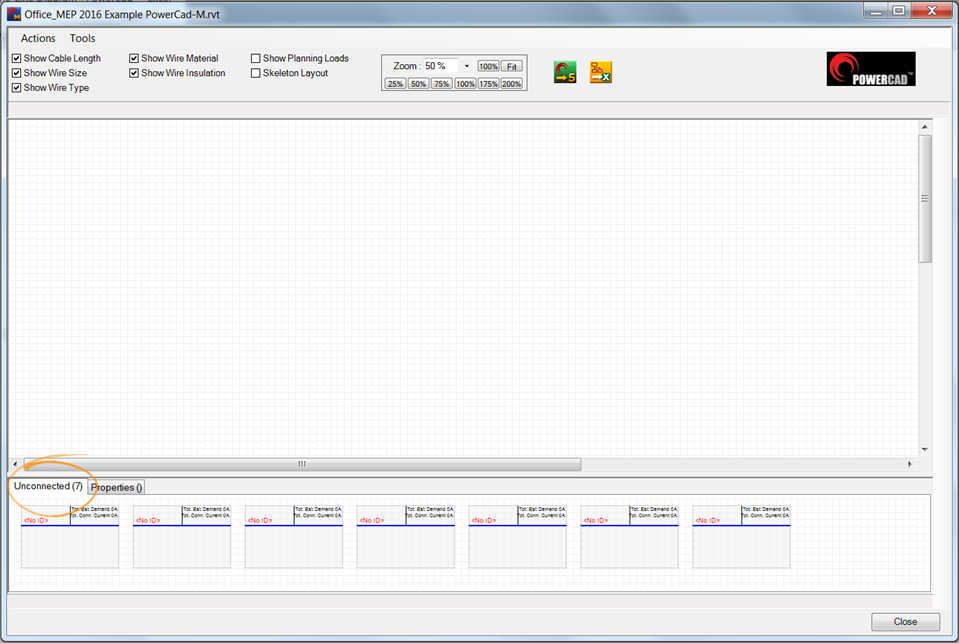
The Panelboards that were added to the Revit® model are not connected to a circuit will appear in the unconnected section of the window.
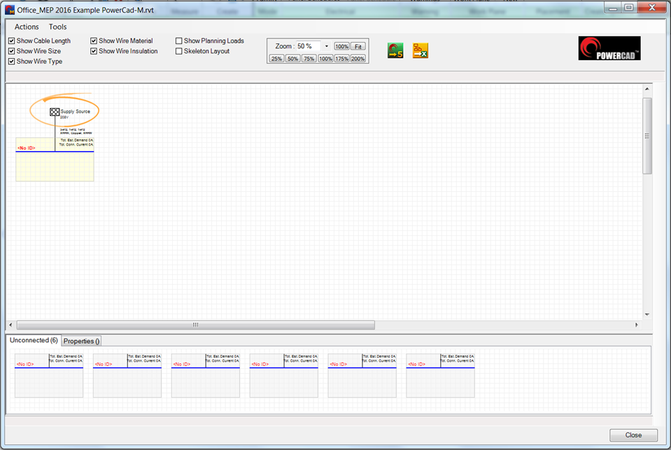
To start building the Electrical network drag and drop the primary board or a transformer into the blank part of the screen. If you are not modeling the transformer PowerCad-M will place a supply source at the top of the electrical distribution.
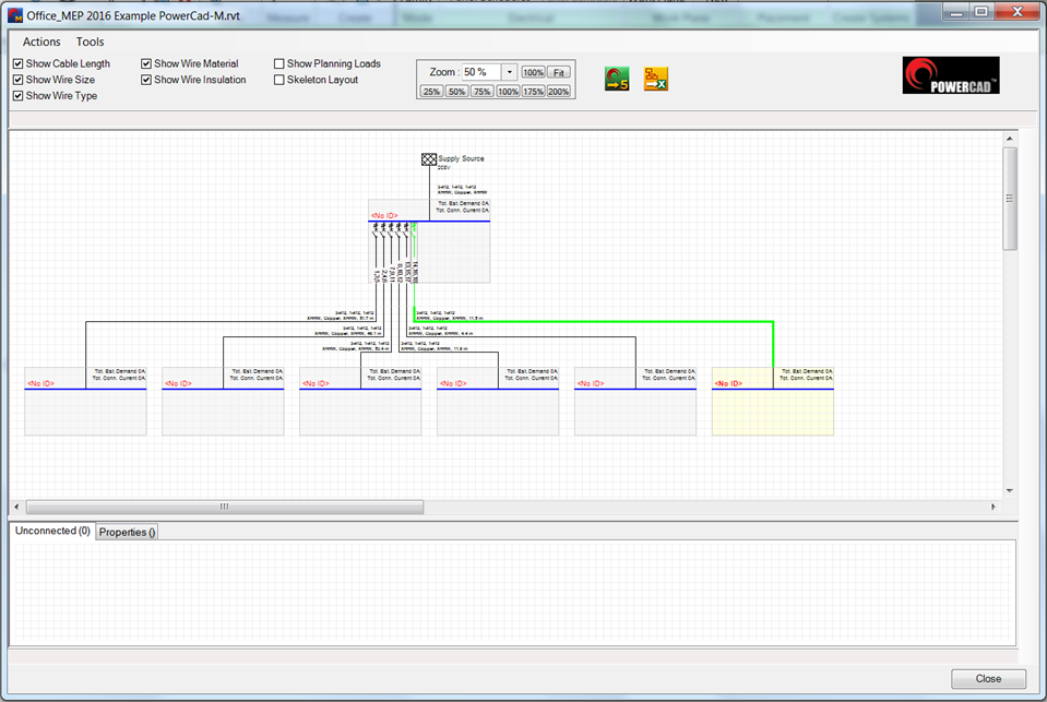
To add boards drag them up from the unconnected region and onto the distribution. If a board cannot be placed because it's on a non compatible distribution system or the number of pole on the upstream board has been exceeded, a warning will appear above the diagram.
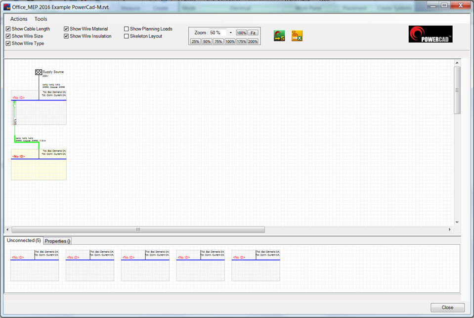
To add boards to your system you simply continue to drag and drop your boards into the diagram. As you drop boards into the diagram the electrical circuiting in Revit is done in the background.
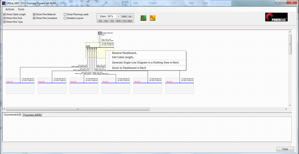
Right click over any board and a menu will appear